Outline of the TASC technology in English
TASC is our novel technology based on the fact that the semiconductor exhibits no catalytic effects at room temperature, whereas significant oxidative properties appear when heated at elevated temperatures at about 350-500 °C. The present effect has been interpreted as arising from thermally generated defect electrons (“hole”) formed in the valence band of the semiconductor. The TASC technology allows us to fragment a giant molecule in an instance into small molecules (for example ethylene and propane) by radical splitting. Then, the fragmented molecules react with oxygen in air to give rise to H2O and CO2 (i.e. complete combustion).
The destruction process is composed of the three major steps: 1. Creation of radicals by oxidation caused by thermal activation of semiconductors. 2. Fragmentation of a giant molecule by radical splitting. That is, the unstable radicals propagate throughout the polymer at 350-500 °C to make the polymer unstable, resulting in the fragmentation of the giant molecule into tiny molecules such as ethylene, propane, etc. 3. Then, the fragmented molecules react with oxygen in air to give rise to H2O and CO2 (i.e. complete combustion).
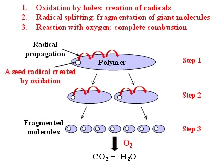
Fig. 1 Schematic diagram of the destruction mechanism of polymers TASC.
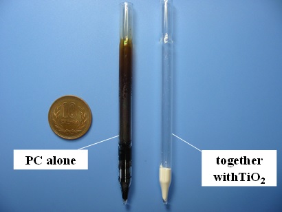
Fig. 2 Decomposition of polycarbonate in the presence or absence of TiO2 used as the semiconductor.
One example is given below of complete decomposition of polycarbonate (PC) which is currently used as the substrate for compact discs. Fig. 2 shows the result of PC decomposition in the presence or absence of TiO2 used as the semiconductor. We carried out our experiment using two glass tubes, each of which contains PC chips. These were heated in air at 500 °C for 30 min. The PC in the absence of TiO2 melted around 200 °C and then boiled, ending up with the carbonization as shown. This is a typical result when a plastic is roasted in air. On the other hand, no trace of PC was recognized in the presence of TiO2. Here remain just white powders of TiO2. Gas analysis of the decomposition product was made by mass spectrometer. Fig. 3(a) shows the result of the experiment carried out in air. We see peaks of N2 (28) and O2 (32) that are components of air, as well as peaks of H2O (18) and CO2 (44). Furthermore, we observe a peak of Ca (40). This is due to a metallic soap of Ca used as a lubricant in optical discs. The present result indicates that the PC whose molecular weight is around 25,000 has entirely been decomposed into H2O and CO2 in an instance. This is an amazing effect! On the other hand, when the experiment was carried out under vacuum as shown in Fig. 3(b), we see a number of small fragments. However, these fragments disappear in an oxygen atmosphere, leaving behind only two peaks of H2O and CO2. This clearly indicates that oxygen is absolutely necessary for the disappearance of fragment peaks. On the basis of these experiments as well as the ESR measurements for radical concentration, we proposed the destruction mechanism as shown in Fig. 1.
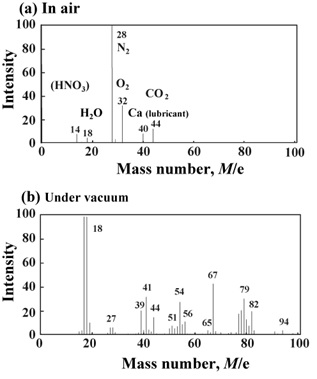
Fig. 3 Mass spectra of the decomposition product: (a) in air and (b) under vacuum.
Then, an important question arises as to what kinds of semiconductors can be used for decomposition, and what kinds of materials can be decomposed by TASC. Those semiconductors which are stable at high temperatures in an oxygen atmosphere come into consideration. This means that oxide semiconductors are the semiconductor of choice. For example, TiO2, ZnO, etc. Among these, we are particularly interested in Cr2O3 that is the most stable compound having a melting point of about 2200 °C. As for the materials to be decomposed, all kinds of thermoplastic and thermosetting polymers, Diesel exhaust which includes benzene, toluene, and PM, and VOC (volatile organic compounds) as well as offensive odor.
1. TASC Applications for the complete removal of polymer matrix in composites
1.1 Decomposition of FRPs and recovery of carbon fiber fabrics
For carbon fiber recycling to become fully commercialized, there are important factors to make a recycling process both technically and economically feasible. Especially, the cost for removing the polymer matrix of the composite plays a crucial importance. To achieve this, we looked closely into the destruction mechanism (Fig. 1) again and focused on the formation of free radicals and their propagation. Then, we felt convinced that the free radicals multiply spontaneously to induce the radical splitting, leading to the fragmentation of the giant molecule into small pieces such as ethylene, propane, etc. This prompted us to believe that we have only to create “seed radicals” in FRP in the initiation process and all the rest proceeds automatically. To sum up, it is sufficient for the FRP plate to be mechanically in contact with Cr2O3 in order to create radicals in the initiation process. This is achieved in the following way.
Fig. 4 shows a Cr2O3–coated honeycomb substrate colored green due to Cr2O3. We simply put an FRP plate on it and then sandwiched by another honeycomb, so that the FRP plate is mechanically in contact with Cr2O3. Then, the plate is heat-treated in air in a furnace.
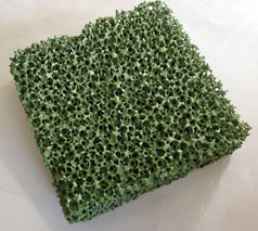
Fig. 4 Cr2O3-coated honeycomb substrate colored green due to Cr2O3.
Fig. 5(a) shows a CFRP plate before TASC treatment. Fig. 5(b) is the plate after TASC treatment at 400 °C for 10 min in air. Polymer matrix was entirely decomposed, giving rise to clean carbon-fiber textiles. Amazingly, no trace of carbonaceous deposits was recognized on the woven textiles.
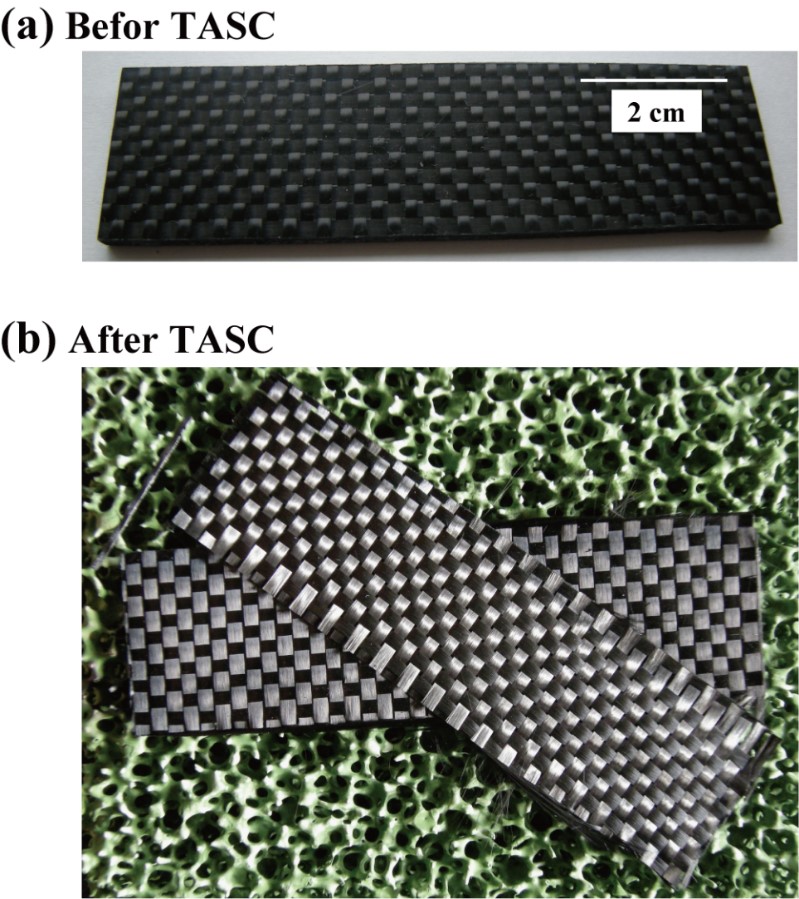
Fig. 5 CFRP plate: (a) before and (b) after TASC processing.
Figs. 6(a) and 6(b) show the SEM (scanning electron microscope) pictures for one single carbon fiber (i.e. one filament), before use and after recovery. No significant difference is recognized in appearance between them.
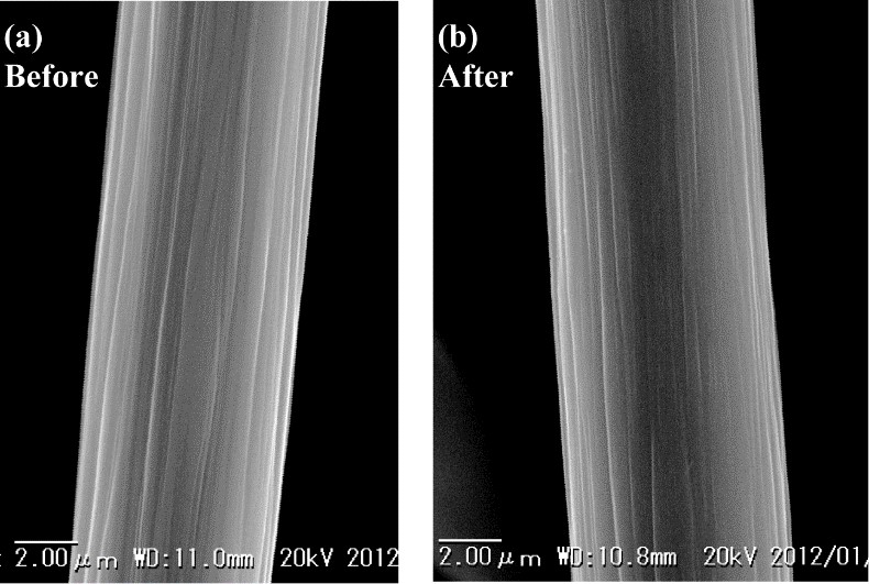
Fig. 6 SEM pictures for one single carbon fiber: (a) before and (b) after TASC processing.
1.2 Continuous apparatus of the FRP recycling system of the tunneling type
Most recently, we have constructed a continuous apparatus of the FRP recycling system of the tunneling type. The process flow is schematically is shown in Fig. 7(a). At the inlet, we feed waste FRPs into the furnace that are sandwiched by two catalyst-coated honeycombs. At the outlet, we obtain recovered carbon-fiber textiles. Exhaust heat caused by the reaction of fragmented molecules with oxygen is recovered and transferred to the inlet. The length of the 500 °C zone is about 1 m, and the transfer rate of FRPs is about 100 mm/min. The process requires about 10-20 min duration and is currently capable of processing FRP wastes up to 200 mm in wide, 1000 mm long and 3 mm thick. The process can be energy self-sufficient using the fragmented molecules processed by TASC as an energy source. Fig. 7(b) shows the prototype of our continuous apparatus of the FRP recycling system of the tunneling type.
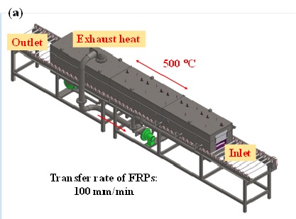
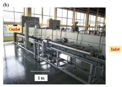
Fig. 7 Continuous apparatus of the FRP recycling system of the tunneling type: (a) schematic illustration and (b) prototype.
Once carbon fibers are recycled from composites as above, there is additional development work that must be performed to incorporate the carbon fibers into new high value applications.
1.3 Recovery of rare-earth powders from resin-bonded magnets
Rare earth metals are nowadays widely used as materials for permanent magnets, polishers of optical glasses, catalysts, phosphors, magnet-optic storage system,etc. The amount of the reserve is said to be about 130 million tons, of which about 48.3% is held by China. In addition, the production of rare earths is centered on China and its market share is about 97% in 2009. The present situation reflects the state of oligopoly (i.e. a state of seller’s market). Because of this, the supply of rare earth metals can easily be influenced by political situations and thus unstable at times. In addition, the price has been constantly and drastically rising every year. In order to obviate the present situation, it is urgently necessary to break up the rare-earth suppliers into several countries other than China. At the same time, we need to accelerate the reclaim and reuse of rare earth metals from the disposals. In view of the above situation, an attempt has been made to reclaim rare earth metals from resin-bonded magnets by decomposing only polymer matrix alone, utilizing the TASC technology.
Resin-bonded magnets are made of magnetic powders together with a minute amount of polymers used as the binder and prepared by means of injection molding in combination with thermoplastic polymers, or compression molding together with thermosetting polymers. Bonded magnets are especially preferred because the magnets of desired shapes can easily be prepared with low costs.
Two kinds of bonded magnets J16 and K12, based upon the composition of Nd-Fe-B/Sm-Fe-N, were obtained from Nichia Corporation. These are tablet magnets (size: 10 mm in diameter and 7 mm in height). The magnets are prepared by injection molding using polyamide 12 (PA12) as the binder for J16, or using polyphenylene sulfide (PPS) for K12.
Bonded magnets of Wellmax S3A (Composition: Sm-Fe-N) were purchased from Sumitomo Metal Mining Co. These are also tablets prepared by injection molding using PA as the binder: 20 mm in diameter and 13 mm in height.
First, the bond magnets were coated with a dispersion layer of Cr2O3 or a-Fe2O3 (thickness: about 5 mm) by dipping the magnets into an acetone suspension containing powders of Cr2O3 or a-Fe2O3. Next, the bond magnets were heated at 500 °C for 20 minutes in air in a muffle furnace in order to decompose the polymer binder into H2O and CO2 on the basis of our TASC technology. The successful result is shown in Fig. 8.

Fig. 8 Pictures for the tablets before TASC (top left and right) and the reclaimed powders after TASC (bottom left and right): J16 and K12 treated with Cr2O3 (left), and Wellmax S3A treated with Cr2O3 or a-Fe2O3 (right).
1.4 Repair of partially damaged FRPs with reinforcing fibers intact
FRPs are widely used in construction related areas.However, once FRPs are partially damaged, there is no way to repair it with embedded reinforcing fibers intact. Currently, so called “scarf method” is used for partial repair which proceeds in such a way as to mechanically remove the damaged area (i.e. both polymer and reinforcing fibers) by a disk grinder, followed by an application of a prepreg together with a binder tape. However, the mechanical strength of the repaired part is greatly diminished because the reinforcing fibers were entirely severed during the repair process. In view of the present situation, a trial has been made to repair partially damaged areas with embedded reinforcing carbon fibers intact, utilizing the TASC technology.
TASC allows us to remove the polymer matrix alone in damaged areas of CFRP in the presence of thermally activated semiconductors while retaining the embedded fibers intact. The polymer-eliminated area is then refilled with an epoxy resin to complete the repair. The repair process is shown in Fig. 9, and the experimental setup is illustrated in Fig. 10. In our experiment, an IR lamp was used together with an ellipsoidal mirror to locally heat the damaged area, using TiO2 as the semiconductor. The FRP plate used for the experiment was prepared as described in section 3.1.

Fig. 9 Schematic diagram of the repair process.

Fig. 10 Experimental setup for the repair system.
Figs. 11(a) and 11(b)show the CFRP plate before and after heat treatment (i.e. TASC), respectively. Fig. 11(c) is a magnified picture of the carbon fiber fabric. The carbon fiber textile looks really undamaged. The depth of the polymer-removed area is about 1 mm, and this can easily be controlled by changing the heating power.
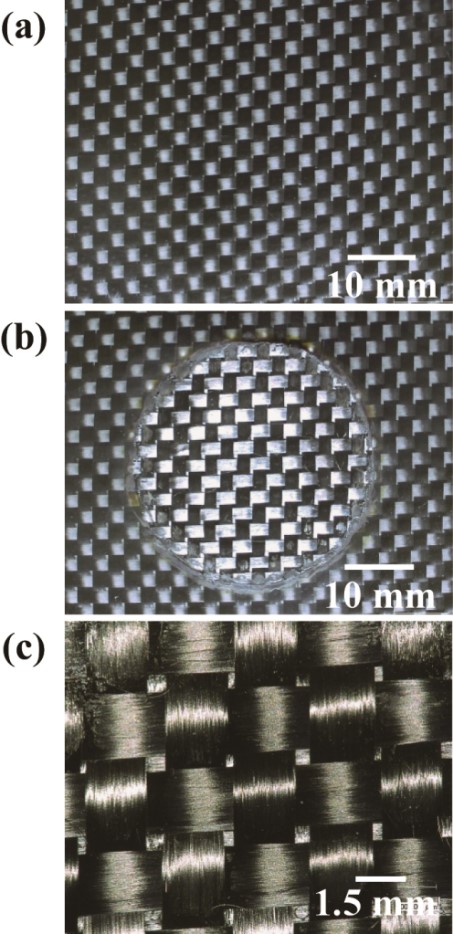
Fig. 11 Pictures for CFRPs: (a) before TASC and (b) after TASC processing, and (c) magnified view of the reclaimed carbon fiber textile.
2. TASC Applications for complete removal of VOCs, tar, and odor
VOCs (volatile organic compounds), tar (which exists in the form of mist at relatively high temperatures) and odor can instantly be fragmented into small molecules of the level of ethylene and propane by the TASC process and ultimately decomposed into H2O and CO2. To achieve this, it is necessary to let VOCs pass through a series of thermally activated catalyst-coated honeycombs.
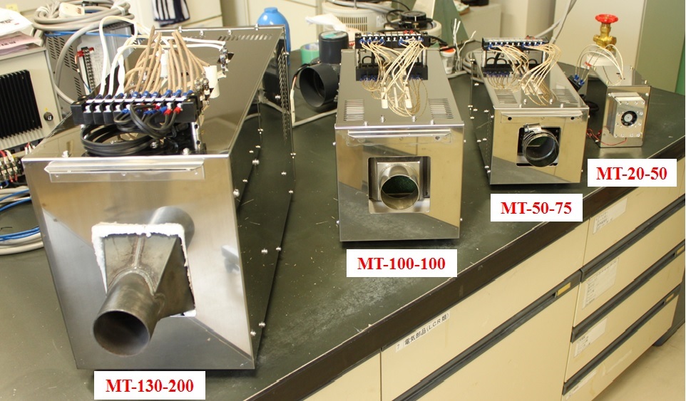
Fig. 12 shows the Cr2O3-coated honeycomb unit which includes a 300 W heate in a groove of the substrate. The dimension of the heater-embedded honeycomb is 130×200×30 mm. Eight pieces of the catalyst unit were stacked in pile and arranged vertically to constitute a catalyst system as schematically shown in Fig. 13(a). Fig. 13(b) is the external appearance of the apparatus. VOC is then made to flow from the inlet through a series of the catalyst units, and the temperature was controlled with two thermocouples placed at the middle and the end of the honeycomb system near the outlet.
The present apparatus (model: MT-130-200) was designed for the flue-gas whose temperature is about 250-300 °C. The maximum operation volume is about 1m3/min when combined with a heat exchanger, while 0.3 m3/min for the flue-gas of room temperature.

Fig. 12Heater-embedded honeycomb unit coated with powdered Cr2O3: 130×200×30 mm.
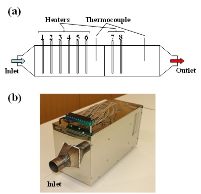
Fig. 13VOC elimination system (model: MT-130-200): (a) schematic representation and (b) external appearance (240×300×560L mm; 20 kg).
Smaller models have also been developed as shown in Fig. 14 which can easily be integrated in office printers, inkjet printers for industrial use and so on.